Diffraction optical waveguide and AR glasses

An optical waveguide and diffracted light technology, applied in the field of diffractive optical waveguides and AR glasses, can solve the problems of poor uniformity of optical coupling and loss of field of view, and achieve the effect of small processing area, avoiding loss of field of view, and improving energy utilization efficiency.

Pending Publication Date: 2022-05-03
ZHUHAI MOJIE TECH CO LTD
View PDF8 Cites 0 Cited by
  • Summary
  • Abstract
  • Description
  • Claims
  • Application Information

AI Technical Summary

Problems solved by technology

[0005] In view of the above-mentioned deficiencies in the prior art, the purpose of the present invention is to provide a diffractive optical waveguide and AR glasses, aimin

Method used

View more

Image

Smart Image Click on the blue labels to locate them in the text.
Viewing Examples
Smart Image
  • Diffraction optical waveguide and AR glasses
  • Diffraction optical waveguide and AR glasses
  • Diffraction optical waveguide and AR glasses

Examples

Experimental program
Comparison scheme
Effect test

Embodiment Construction

[0046] In order to facilitate the understanding of the present invention, the present invention will be described more fully below with reference to the associated drawings. Preferred embodiments of the invention are shown in the accompanying drawings. However, the present invention can be embodied in many different forms and is not limited to the embodiments described herein. On the contrary, the purpose of providing these embodiments is to make the disclosure of the present invention more thorough and comprehensive.

[0047] Unless otherwise defined, all technical and scientific terms used herein have the same meaning as commonly understood by one of ordinary skill in the technical field of the invention. The terminology used herein in the description of the present invention is only for the purpose of describing specific embodiments, and is not intended to limit the present invention.

[0048] It should be noted that when a component is referred to as being “fixed on” or ...

Login to view more

PUM

No PUM Login to view more

Abstract

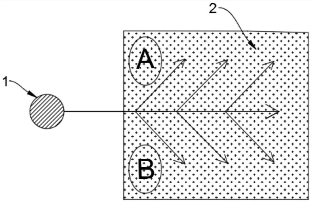
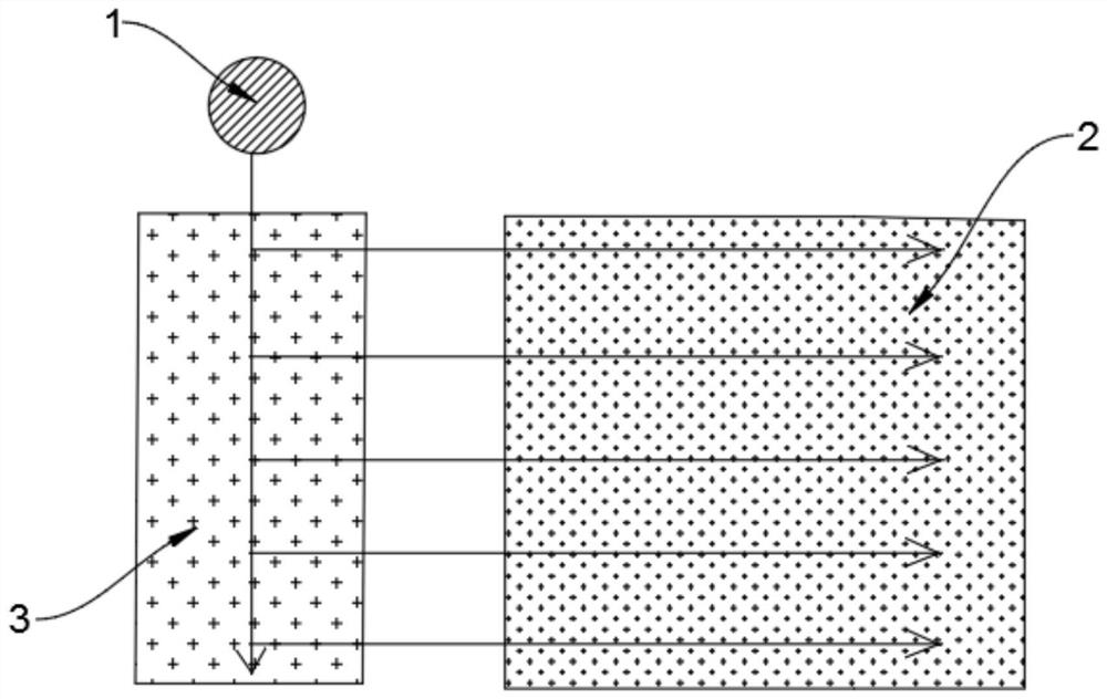
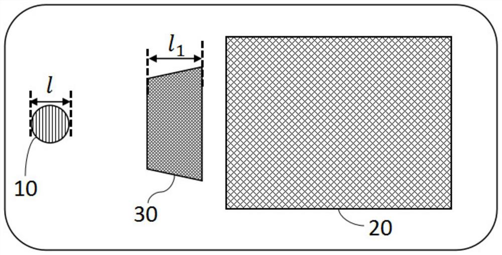
The invention relates to a diffraction optical waveguide and AR glasses. The diffraction optical waveguide comprises an optical waveguide substrate, and a coupling-in region, a relay region and a coupling-out region which are arranged on the optical waveguide substrate, each relay area is arranged between the coupling-in area and the coupling-out area; the coupling-in grating is arranged in the coupling-in area and used for coupling light into the optical waveguide substrate and transmitting the light to the relay area and the coupling-out area; the relay grating is arranged in the relay area and used for changing the transmission path of the light so that the light can spread all over the coupling-out area; and the coupling-out grating is arranged in the coupling-out area and is used for coupling out the light from the coupling-out area. According to the invention, the relay grating can change the transmission path of a part of light, so that the light coupled from the coupling-in grating can be transmitted to the coupling-out area through the relay grating and covers the whole coupling-out area, the problem that the coupling-out area has a field-of-view dark corner is avoided, and the energy utilization efficiency of the light is improved at the same time.

Description

technical field [0001] The invention relates to the technical field of light emitting devices, in particular to a diffractive optical waveguide and AR glasses. Background technique [0002] In the augmented reality (Augmented reality, AR) and mixed reality (Mixed reality, MR) fields, compared to Bird Bath (BB, transflective), insect eye (off-axis reflective), free-form prism and other display solutions, light The waveguide solution is lighter and thinner, and the eye box is larger, so it has broader application prospects. The eye box refers to the two-dimensional area where the human eye can completely see the light of the given field of view (complete virtual image) at a given viewing distance. In the optical waveguide solution, compared with the array optical waveguide using a partially transflective film, the manufacturing process of the diffractive optical waveguide is less difficult, and there is no grid-shaped dark when realizing two-dimensional pupil expansion (exit ...

Claims

Login to view more

Application Information

Patent Timeline
no application Login to view more
IPC IPC(8): G02B6/00G02B27/42G02B27/00G02B27/01
CPCG02B6/0016G02B27/4272G02B27/0081G02B27/0172G02B2027/0178G02B2027/0174
Inventor 邵陈荻关健兰富洋李竹
Owner ZHUHAI MOJIE TECH CO LTD
Who we serve
  • R&D Engineer
  • R&D Manager
  • IP Professional
Why Eureka
  • Industry Leading Data Capabilities
  • Powerful AI technology
  • Patent DNA Extraction
Social media
Try Eureka
PatSnap group products